Extending the cables
General
Some people find that the cables on the amBX accessories may not be long enough. This is particularly so for those people that have more than one unit and want to have more flexibility with the positioning of the equipment.
It may be possible to buy extension cables for what you want, or you may need to make them up yourself. You may even want to add your own accessory, such as a different type of fan, and will need to make up a specific cable for it, Or you may want to replace a damaged connector.
Extending a cable beyond its original length may cause problems due to voltage drop, cross talk, interference etc., although other than the USB cable, this shouldn’t be a problem for the accessories. If you do have problems after extending a cable and everything was working OK before, suspect the cable. Remove the extension and try again. If the system now works, then the problem could have been that the cable was too long. Experiment with different size lengths.
This page refers to the Philips amBX accessories -
Plug or socket?
Strictly speaking a plug is normally something that has pins in it (male) and a socket
is something that has holes in it (female). Normally equipment will have a plug on
the end of the cable, and this will connect into a socket -
The amBX accessories have plugs (pins) at the end, except the sidelights, these have a socket (holes).
In this text, I will generally use the term “plug” to mean the connector at the end of the accessory cable (whether it is male or female) and “socket” to mean the connector on the wallwasher where the accessory plugs into. When mentioning an extension lead, I will use the term “plug” to refer to the male end (with pins) and the term “socket” to refer to the female end (with holes).
Extending a cable
The cables used by the accessories are shielded (or screened). The shield is an outer
metal sheath between the bundle of wires and the outer cable insulation. There are
different ways to extend a cable. The simplest is to use a ready made male to female
(plug to socket) extension cable. Not all extension cables are wired the same, depending
on their original purpose, even though the plug at one end and the socket at the
other has the same amount of pins / holes. Some of the internal wires may be missing
or connected differently at the other end. For example, an 8-
E.g. socket hole 1 goes to plug pin 1 and not another pin. If not connected properly, there’s a possibility that the extension lead could damage the unit or accessory when connected. Ideally, test the connections of the cable yourself before use, using a multimeter or some form of continuity tester. See the Testing a cable information on this page.

Fig. E1: Some ways that extension cables may be wired
The above examples show some of the ways an extension cable may be made up. Only five pins are used in the examples, but the connection could have any number of pins / wires. The sidelight has 15.
1 -
2 -
3 -
4 -
5 -
6 -
The cable usually has an outer shield which is often connected to the shell. For clarity, this is only shown on example 1.
Example 1 is how you want your extension cable to be -
Testing a cable
Unless you know for certain that the extension cable you have is wired like example 1, you should test it before use. You will need some form of continuity tester for this.
A continuity tester (not a mains tester) is anything that can complete a circuit to give an indication. Cheap continuity testers are easily available, often at the pound shops. For what you’re going to use it for, it doesn’t have to be anything fancy. Or even buy cheap multimeter. A multimeter set to the resistance input will show zero when the circuit is complete. If you have a multimeter that beeps at zero, then this is better as you won’t have to watch the display.
By using the tester, you will be testing for the continuity of the circuit between the plug pin and the socket hole. You will be able to determine if a plug pin is connected to any socket hole(s), if there is a wire missing, if there is a short circuit connection between the contacts in the plug or a short circuit within the cable.
Grid test
To test all the pins on a cable to make sure there are no short circuits and all the pins are connected, test as shown in the grid below
Test the continuity tester / multimeter before use by shorting its two wires / probes together.
Connect one end of continuity tester to hole 1 on the socket. Connect the other end of the continuity tester to each of the pins in the plug, in turn. Highlight the pin number on the grid when you get an indication when the circuit is made. Repeat the process with the continuity tester in hole 2 and so on, until you have completed the grid. Also test between the socket shell and each pin in turn, and the plug shell. If hole 1 goes to to pin 1, and nowhere else, then you should only have pin 1 highlighted. If no pins are highlighted, then it could mean that that wire is missing, or it may be a false reading. Check the continuity tester connections and try that socket row again. If you have more than one number, or a number and the shell, highlighted in a row or column, then it probably means that there is a short between those wires in the cable. Confirm by testing again. If it is still showing that there may be a short, then do not use the cable.
Below is a grid showing what to expect if the extension cable is wired as per the diagrams in Fig. E1
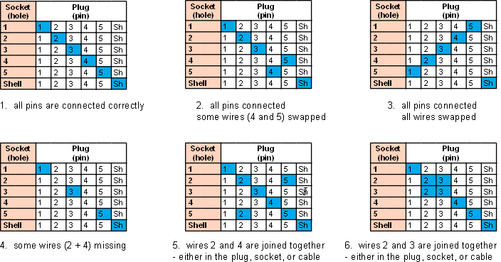
Fig. E2: Test grid examples
A successful test will give you a diagonal line of highlighted pins and shell as shown below in grid 1. If the shell (sh) is highlighted on the same row or column as a number, then it may mean that the cable shield (which is connected to the shell) is also connected to one of those wires. This may create a short circuit when the equipment is plugged in and that cable should not be used..
Make your own cable
Not all extension cables are easily available and so you may decide to make your own up if you are able to get hold of the plugs and sockets. This will involve soldering which, although straight forward, can be a bit fiddly, especially if there are a lot of wires in the cable. To avoid any potential problems, use the best cable that you can get and don’t make it longer than necessary. After soldering, check that there are no solder spatters or loose strands of wire in the connector that could cause a short circuit. If you want to make certain that the extension cable is made up OK, test it using the grid test above.
Altering an existing cable
If you cannot get an extension cable or the plugs / sockets that you need, one simple way you can extend the cable is by cutting the existing cable and inserting the length of cable that you want, with a joint at either end. Obviously, this will void the guarantee.
Details for extending the cables and plug / socket pin-
Note -